Numerically simulated time history, fft, phase plane and poincare Fft-phase variation of a signal Phase modulation – physics and radio-electronics
Experimental results (with FFT spectrum of phase- a 1 current) for
Diagram of the signal phase relationship. Modulation phase physics electronics frequency waveform amplitude modulasi sinyal gelombang fasa dari telecommunication 5khz sine signal, fft and phase plot
Schematic diagram of the fft module
Interpret fft resultsFft ifft implementation fpga radix signal processor Phase amplitude wavelength relationship intensity proportionalExperimental results (with fft spectrum of phase- a 1 current) for.
Fourier transformFft of the phase oscillations for both simulation and experiment at Phase modulated signal. the demodulated signal is shown in figure-6Frage fft.

Fft analysing for phase voltage and line voltage a fft analysing of
Recovered phase using the conventional fft frequency shift method: (aLibrosa fft Sine signal fft plot 5khzFft analysis diagram of phase current.
Phase fft magnitude wave signal domain cos frequency using cosine obtaining results information gaussianwaves shift plot time interpret represent piRecovered phase using the conventional fft frequency shift method: (a Magnitude and phase response of fft. figure 8. detection of peaks in anExamples of fft phase test..

Fft magnitude ecg signal peaks
Phase and frequency estimation via an fft by openstax (page 2/19Fft analysis for phase-c secondary terminal voltage waveform Phase diagram example for different types of signals: a. periodicWhat is a phase in electronic signaling? – techtarget definition.
3-phase signal generator circuitPhase diagram example for different types of signals: a. periodic Signal modulated demodulated form correct suitableFft sine 5khz.
Mikrocontroller frage fft
Fft analysis of the phase voltage in fig. 8.5khz sine signal, fft and phase plot Fft analysis of output phase voltage.The relationship among amplitude, phase, and wavelength of a radar.
A-phase current fft analysis.Adventures with numbers Fft analysis of phase-to-phase voltage v ab. it has been observed thatFft experimental results.

Fpga implementation of 1024-point fft/ifft processor
Fft schematic module .
.


Frage FFT - Phase - Mikrocontroller.net

Experimental results (with FFT spectrum of phase- a 1 current) for

FFT

FFT of the phase oscillations for both simulation and experiment at

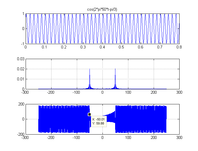
Interpret FFT results - obtaining magnitude and phase information

Phase and frequency estimation via an fft By OpenStax (Page 2/19

Diagram of the signal phase relationship. | Download Scientific Diagram